TubeWaysSolar traffic system
~~~~~~~~~~~~~~~~~~~~~~~~~
T U B E
W A Y
S O L A R The future of energy and mobility will be solar!
~~~~~~~~~~~~~~~~~~~~~~~~~ >> T U B E - W A Y - S O L A R <<

Michael Thalhammer
TUBEWAYSOLAR - Development and concept study on solar-powered pipe routes for climate-neutral mobility
Foreword:
It was in the early 2000s when the idea of a pneumatic tube system became a modern transportation system. TubeWaySolar was born. TubeWay could be the answer to many of the challenges of our time: firstly, to ensure long-term, affordable mobility, and secondly, to prevent further environmental pollution from CO2, noise, and fumes. 🌞 It was clear to me that the 24/7 power supply should come exclusively from the sun. The tube corridor, covered with PV films, generates an abundance of electrical energy from daylight that can be fed into the electricity market. TubeWay glides smoothly, quietly, and emission-free in durable, low-maintenance tube sections – and would have the capacity of a six-lane highway. Speeds of around 150 kilometers per hour could be achieved. TWS routes would run on elegant elevated tracks at an average height of seven meters. TubeWay requires very little land. Naturally developed habitats would be preserved for people, animals, and agricultural use. TubeWay would provide crucial connections to various hubs and offer structural services for passenger and freight transport. Safety is paramount at TubeWay: the entire network would be controlled and monitored via computer-aided control centers. My primary concern is that we preserve our unique planet and maintain our shared habitat. TubeWaySolar helps to advance the energy and mobility transition. earthsolar.info #EnergyandMobilitywillbeSolar
Minimal description (supported in parts by AI)
A modular, solar-integrated traffic and transport corridor: emission-free, low-noise, and environmentally friendly. "TubeWaySolar" combines photovoltaic-powered energy supply with lightweight, low-maintenance pipe infrastructure—for passenger transport, freight logistics, and local power generation.
TubeWaySolar is a scalable transport system consisting of covered pipe sections with integrated photovoltaics. Modular cabins/capsules (C/C) glide within protected pipes with low friction losses, powered by solar-generated electric modules. The system reduces land use, emissions, and operating costs—while simultaneously supplying renewable grid energy.
Why TubeWaySolar? (Key Statements)
Emissions & Noise: Fully electric, protected within the pipe → virtually no local air pollution or noise emissions.
Land and nature conservation: Lightweight elevated routes instead of wide clearings; soils remain usable for agriculture.
Integrated value creation: PV arrays on pipeline routes generate electricity for the grid and operation—an additional source of revenue.
Scalability: Modules (22 m) and standardized sliding segments enable phased expansion: pilot → regional grid → corridor networking.
Cost efficiency: Lower operating costs due to low friction, simple substructure, and mass-producible components.
Technical concept—brief overview
Track construction: 15 m long sandwich tubes (1.2 mm stainless steel outer and inner shell; — rigid, insulated, durable.
Inner tube diameter: approx. 1.6 m — cabin maintenance, evacuation and technical access.
Stationary: Cabin 22 m long, side entry, 3 rows of 75 seats or 15 pallets.
Pneumatic: 24/7 operation, no fighting against air.
Speeds: around 120 km/h average speed.
Cabins/Capsules (C/C): Articulated segments of 4 m; convoys of up to (pneumatic) 40 segments per electric locomotive. Soles with PTFE sliding pads, pneumatic micro-lift for friction optimization.
Drive & Energy: Solar panels on the tubes provide primary energy; electric locomotives with regenerative braking supply/distribute power. Buffer storage ensures operational readiness.
Support and Suspension Concept: Lightweight bridge arches with high-performance fiber ropes (e.g., HyperTEN / chaRope) for long spans (e.g., 80 m) — significant weight savings compared to steel.
Safety & Monitoring: Centrally controlled control center, sensor systems for friction, temperature, and rope condition, redundant compressors/emergency brakes.
Economic Leverage & Business Model
Dual revenue streams: Travel/transport revenue + electricity sales from integrated PV production.
... Added value: Reduced external costs (noise, CO₂, land sealing), regional jobs through mass production.
Financing options: Public-private partnership (PPP), EU infrastructure funding programs, impact investors, pilot financing via local networks.
Scaling strategy: Prototype → 40cm-tube network (pilot corridor) → 160-tube SiS network (scaling).
Safety, testing & verification
TubeWaySolar is a new infrastructure concept and requires phased verification:
Laboratory/tribology tests (pad/steel, abrasion, temperature).
CFD simulations (pipe flow, pressure waves).
Structural FEM verification (pillars, cable arrangements, fatigue).
Field prototype (e.g., 1-voltage / 100–500 m test track) with monitoring and lifetime measurement. Large-scale deployment is only justifiable after successful test runs. (Recommendation: Collaboration with universities, material manufacturers, traffic engineers, and regulatory authorities.
Environmental & Social Compatibility
Nature Conservation: Minimized land requirements, accessible agricultural land, visual integration through elegant routes. Contributing to the 1.5° climate target.
Social: Creation of locally based jobs, affordable mobility for regions with poor connections, more livable landscapes for future generations.
How to Participate / Next Steps
Now its need: Pilot partners, research partners, municipalities with pilot sites, investors for a 40-kilometer pilot corridor. If you are interested in: a technology partnership, a feasibility study, or prototype financing — contact us for a confidential discussion.
Contact: LinkedIn/ Group/ TubeWaySolar
____________________
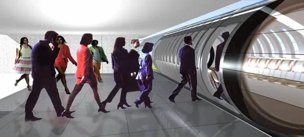
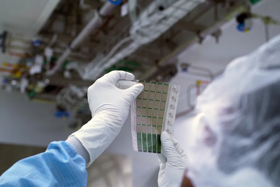
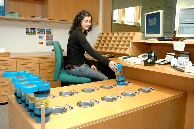 Image of a modern pneumatic tube system.
In 1819, the Scottish engineer William Murdoch demonstrably conducted a series of experiments with compressed air and developed the first pneumatic communication system, which later became known as pneumatic tubes.
TubeWaySolar is, in some respects, still quite similar to a pneumatic tube system, even technically.
See also my video here: www.youtube.com/watch?v=19YDKukm2vc&t=18s
>>The following sections will discuss the key business aspects, as well as the technical functions and their system security in more detail:
Part 1
What are the business aspects of TubeWaySolar?
The transport revolution requires new business models that are both profitable AND sustainable. The TWS transport infrastructure sells its surplus solar power to the grid via a "solar-integrated transport corridor." This allows TubeWay to maintain its own energy supply free of charge AND position itself as a major electricity provider.
While some upfront investments and carefully planned implementation steps are necessary for TWS's mobility service, once established, investors and operators could generate consistently secure profits. For example, the extensive technical expertise of Siemens Mobility, Alstom, ÖBB, and the EU infrastructure can be combined to achieve success through TubeWay. TubeWaySolar—as a particularly efficient complement to existing modes of transport—paves the way for an economically and ecologically sound restructuring.
The market for public transport and freight logistics in Europe is worth over €200 billion annually. TubeWay aims to establish its sustainable contribution with low operating costs, new revenue streams (tickets, transport fees, solar power sales), and its high scalability across all locations. This would simultaneously create a variety of business sectors. For example, the legal structure could be such that the pipelines are nationally owned, the solar energy is supplied by a public limited company, and the vehicle fleet is under the jurisdiction of a public administration. Several hybrid models are possible.
Europe has THE opportunity to secure outstanding technological leadership with TubeWay – or to lose it to other regions. TubeWay-Mobility has the potential to revitalize key segments of our market and working world. This creates a win-win situation for customers, operators, and our immediate environment.
>Expertise from investment, EU infrastructure planning, and the relevant industries is needed. Now, a suitable capital consortium with an affinity for EU policy and major industry is required<.
Truly reliable figures are rare for large-scale projects, and I cannot offer any here either – however: The preliminary development can be carried out – with low financial risk – using the technically identical 40 cm network, which is suitable for a wide range of applications. This also generates the 160 cm SiS network in a step-by-step financing plan.
Oil crises and rising energy costs do not affect TubeWaySolar; in fact, they indirectly even fuel its growth. However, the constant increase in CO2 emissions (climate change) also demands immediate action! TubeWaySolar would be its most direct way to combat this problem. Limiting factors.
Global growth regions urgently need sustainable infrastructure. TubeWaySolar can unleash its dual potential here: CO₂ savings in the gigaton range CO2 AND new economic prospects. But the question remains: Who will take this path first – Europe or other regions of the world?
Whoever scales up first in TWS will have a global advantage!
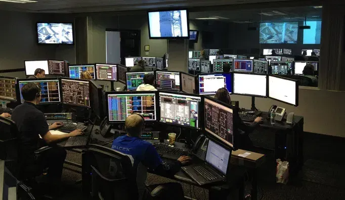 Control centers of future TubeWays (example image)
Market – Competitors – Strategy
Railway lines cost (in 2017) an average of about €27 million per kilometer. Building a highway costs up to €70 million per kilometer (2014). These costs do not even include the cost of acquiring the land for there route.
Early adopter advantage: Europe can secure technological leadership – or leave it to others.
Advantage: Industrial series production instead of individual projects.
Economically and ecologically sustainable: low operating and maintenance costs, secure revenue streams – ticket and transport fees, & solar power grid feed-in.
Rail lines, on the other hand, are hampered by the high pressure to modernise – with falling, conspicuously low residual values. In comparison, railway tracks are far more serious; they are bulky and also divide up the landscape.
What are the business aspects of TubeWay? In other words, what existential tipping points are fundamentally affecting rail transport, which is still considered moderate today? How many tonnes does a high-speed train set weigh in comparison? And how expensive are tracks, superstructure, locomotives, etc.? TWS is setting the course for an economically sensible reorientation!
Growth regions: EU, India, China, Africa with high infrastructure needs.
Addressable market: European public transport + freight logistics > €200 billion/year.
ESG investments: > €1 trillion in sustainable funds; high demand for green infrastructure.
PPP (Public-Private Partnerships) - Green Bonds & ESG financing.
Cost structure: One-time high CAPEX (construction, R&D) - Moderate OPEX (maintenance, virtually free energy).
Risks: If Europe does not adopt TWS and similar concepts, other regions could scale these technologies first. That would be a double loss: technological and geopolitical.
Part 2:
TECHNOLOGY from TWS / TubeWaySolar - TW-SiS
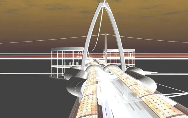
The TWS is illustrated here as a "sit-in-surf" (TW-SiS) system. Its connections would be of great benefit as regional transport networks, as well as in the InterCity transport sector; admittedly rather simple and modest, but "more sustainable than the still common, hasty grandiosity".
 TubeWays are fundamentally designed as bidirectional tracks, held parallel to each other by flexible spacers. Support cables, interconnected tubes, and arched piers ensure the necessary safety for the track, which is typically suspended at a height of 7 meters.
The bridge's structural design supports a bidirectional track, the sliding units, and the utility line. The tension cables are ultralight fiber ropes from Teufelberger's HyperTEN+ and Pro-P or Trowis ChaRope®. They are stronger, 80% lighter, more durable and cheaper than steel, with water-repellent properties and high UV stability.
Each arched pier bears approximately 30 tons of track weight plus an average of up to 9 tons of traffic load. These slender pillar arches are suspended using vibration-free tension cable technology (plus spiral-wrapped vibration dampers) to keep their sections on course. The distance between the pillar arches is approximately 90 metres, and each pillar rests on a base foundation measuring just 50 x 50 cm.
“In comparison, the railway track infrastructure, consisting of the superstructure with rails, sleepers, and ballast, is more cumbersome; it is bulky and also fragments the landscape. Even all the combustion engine cars and highways are only a short step into the future.”
The 15-meter-long track modules (each weighing approximately 6 tons) are constructed as rigid sandwich tubes. The inner and outer shells are made of 1.2 mm thick stainless steel, which is corrosion-resistant, durable, and requires minimal maintenance. Both tube layers are connected by twelve radially arranged longitudinal ribs. These ribs are spot-welded using electrical resistance welding and provide torsional and flexural rigidity to the module along its entire length.
Fire protection – safe pipe insulation
The twelve segmented chambers between the inner and outer pipes are completely filled with non-combustible mineral fiber insulation of building material class A1 (e.g., basalt fiber/rock wool). This measure fulfills several safety-relevant functions:
# effective fire protection: Rock wool only melts above 1,000 °C
# prevention of fire propagation within the pipe system
# damping of structure-borne noise and vibration transmission
# thermal stabilization of the internal climate within the pipe
# no toxic smoke in case of fire (unlike XPS or PU)
This effectively mitigates the potentially most critical scenario – a fire in a closed pipe system.
Each module thus forms a high-strength, surprisingly lightweight, and simultaneously elastic unit suitable for decades of exposure to terrain, wind, and weather. The tube ends are equipped with socket joints that, thanks to precisely inserted O-ring seals, provide a flexible expansion joint. This allows for temperature-related changes in length without compromising structural integrity.
In ecologically sensitive areas, track construction is carried out using half-length modules to minimize the impact on the terrain. Delivery is made by cargo helicopter, which precisely positions the modules while suspended. This allows for quick and ground-friendly installation of the suspension points, without the need for additional access roads or heavy agricultural machinery.
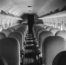
All 22-meter-long cabins or capsules (C/C) glide towards their pre-coded destination in a permanent air stream.
The windowless cabins offer passengers a choice of music, short films, or a landscape displayed on a monitor. The 75 lightweight folding seats offer modern travel comfort with folding tables monitors and internet access. Luggage can be stored in the overhead compartment and at the passenger's legroom. The rows of three seats are ventilated with pleasantly filtered, tempered fresh air from the air conditioning system.
The interior cabin floor consists of 3 mm aluminum checker plate with a cork backing. Its longitudinal profile provides horizontal flooring for the two passengers sitting on the outside; the legs of the third passenger rest on the middle floor of this profile, meaning that they sit slightly lower.
Two meters of the interior are dedicated to accommodating strollers, bicycles, and wheelchairs.
Toilets are only available at larger stations.
Each cabin or capsule (abbreviated "C/C") glides towards its pre-coded destination in a continuous airflow. They glide on the highly polished, cork-lined stainless steel inserts of the inner tube.
The soles of the K/K have four parallel Teflon sliding pads**, each measuring 3.6 m × 0.5 m and 2 cm thick. Each PTFE-pad has an 8 mm deep longitudinal recess (3.2 m × 1 cm), from which a minimum lift of approx. 0.1 mm is generated at 4x4 points by an on-board compressor.
In a state of micro-levitation, the pads carry up to 950 kg per K/K segment with a PTFE sliding pad friction coefficient of approximately μ ≈ 0.01 – in a state of micro-levitation; without an air film: μ ≈ 0.04–0.08 at speeds of up to 120, max. ~150 km/h***. The aluminium honeycomb chassis underneath provides efficient heat dissipation and high structural rigidity.
"... (subjective) AI conclusion: PTFE sliding pads could well be more economical and operationally sensible for the TWS concept — if everything is cleanly designed, well maintained and operationally disciplined. Pads are cheaper to use than traditional systems. If I were to build today — with the pipe route + PV + lightweight construction — I would prefer sliding pads because maintenance, noise, infrastructure costs and environmental impact are significantly lower than with rubber wheels or rails."
The pads are enclosed in multi-point clamping profiles and secured by secondary retaining clips. Optional recommendations include an upstream air curtain for particle reduction, replaceable sacrificial strips, and temperature and wear sensors for predictive operational monitoring.
To ensure "constant airflow under hermetic conditions," a series of multi-chamber felt seals surrounds each C/C cylinder. The profiles, which are open towards the pipe wall, form rotating air roll rings in circular recesses along the inner wall of the pipe. The overpressure dynamics of these ‘air rolls, which feed themselves as they move,’ prevent any flow of the propulsion medium. These multi-chamber profiles work without directly touching the pipe wall. The electric locomotives are also surrounded by several such seals.
The aircraft-grade aluminum sandwich chassis of the "C/C" features an internally structured aluminum honeycomb pattern. Both vertical panels of the cabin incorporate emergency exit sliding doors and anti-noise reduction units.
_____________________
AI says: Brief summary
TubeWaySolar
+ High energy efficiency, low complexity + Low construction and operating costs + Positive energy balance thanks to PV corridor + No vacuum risks, simple emergency technology − No extreme speeds, but rather a focus on medium distances/regional transport
TWS wins in terms of: cost, operation, energy, safety, scalability.
Hyperloop
+ only hypothetical advantage would be extreme speed − technically, economically and safety-wise hardly feasible − systemic risks (fire, evacuation, vacuum loss, pumping costs)
Hyperloop loses: Feasibility, costs, energy, safety.
Rail
+ Proven, efficient, safe − Expensive to build and maintain − High energy dependency − No own energy production
Rail wins: Throughput, standardisation, but will lose out to energy-positive systems in the future.
_______________
AI-Comparison of TWS vs. Rail
System principle: Passive sliding transport in an atmospheric tube, PV-supported, low pressure differential. // Steel wheel on rail, overhead line, or diesel.
Energy source: On-site energy production via PV corridor; very low operating consumption. // High power demand (electric locomotives), no energy gain.
Energy efficiency: Very high - μ ≈ 0.01; lightweight construction; low air resistance. // High to medium (efficient wheel-rail system).
Speed (≈): Designed for 60-150 km/h (optimized for energy vs. throughput). // 160-320 km/h (high speed).
Construction costs per km: Low to medium (lightweight tube, PV contributes to costs). // Medium to high (rails, bridges, signaling technology).
Operating costs: Very low (surplus PV energy, few wear parts, no vacuum). // Medium (rail/overhead line maintenance).
Overall energy balance: positive (PV > operating energy demand). // neutral to negative.
Structural requirements: Lightweight hollow tubes, cable structures possible. // Heavy structures, bridges, tunnels.
Fire safety: High (atmospheric, mineral insulation, low speeds). // Medium (tunnels critical, but manageable).
Evacuation: Relatively easy via side emergency exits. // established and well-managed.
Maintenance: low (little mechanical stress, standard PV modules). // medium to high.
Noise emissions: very low. // medium to high.
Scalability - Pilotability: very high (100-m low pilots immediately possible). // high.
Technological maturity level (TRL): 3-6 (mid-range, known components, new combination). // 9 (mature technology).
Ecological footprint: positive (PV covered). // neutral to negative.
Capacity - Throughput: medium, up to 15,000 passengers/hour. // high, up to 50,000 passengers/hour.
Risk - Security systems: moderate and manageable. // established.
------------------------
The TWS offers cargo capacity of approximately 15 pallets per capsule, with a total weight of of approximately 5 tons of freight. Freight forwarders direct their goods to the designated TW connection terminals. Hazardous goods, as well as heavy and container transport, remain the responsibility of road freight by truck and the established rail park-and-rail system. They cannot and may not be transported on TW.
To ensure more even utilization of TW routes, freight carriers receive a slightly lower per-kilometer rate during the night hours from 9 p.m. to 7 a.m.
TW Sit-in-surf and TW Cargo offer a high overall transport density through connections to major passenger transport hubs and freight distribution centers. Within cities, the routes run just above buildings and partially rest on top of them.
The freight sector will shift its focus to the more profitable e-truck fleets and subsequently to the "future TW logistics handling."
** What is PTFE (Teflon)? It possesses an unusual combination of outstanding chemical, physical, and electrical properties, unmatched by any other plastic to date. PTFE's temperature resistance ranges from -140°C to +260°C, and even up to +300°C for short periods. Teflon has a very low coefficient of friction, with static and sliding friction being equally low. Furthermore, compared to current rail wheels or rubber tires, Teflon is extremely cost-effective and lightweight. It will probably be a wear-balanced compound with good long-term performance and high contamination tolerance.
• PTFE: 60–75 wt% • Graphite: 8–12 wt% • MoS₂: 5–10 wt% • Short carbon fibre: 3–8 wt% Effect: Significantly lower wear, more stable μ under contamination, better heat dissipation; slightly higher density. Application: High-traffic sections, dusty environments, longer operating times.
*** The TW-SiS operates at a maximum speed of 85 km/h in urban areas and up to 220 km/h in regional areas. All dimensions given here are approximate and represent only the general concept.
Now to the propulsion system
At intervals, electric locomotive propulsion units push/pull the C/C assigned to them. They move these C/C by pneumatically transmitting suction or pressure to their front and rear vertical deck plates. With a high degree of smooth sliding, they ensure a continuous, continuous flow of air.
The energy for the electric locomotives is supplied by solar PV-thinfilms covering the pipe sections. Each electric locomotive carries up to 40 C/C. Each locomotive can also reverse, pushing and pulling as needed. Each locomotive has two drive wheels – one at the front and one at the rear – which are almost as large as the surrounding pipe. The pair of solid rubber-tired wheels can be made of carbon fiber or aircraft-grade aluminum.
The articulated electric locomotives, approximately 5 meters long, follow a logistical work schedule and, when necessary, switch to the opposite track via reversing loops or into standby loops.
These articulated electric locomotives follow a logistical work assignment and, if required, switch to the opposite track via turning loops or into standby loops. The ideal passenger volume for the TW system is 5 to 25 passenger units per hour, as recorded at measuring points.
For r=15 passenger units/hour: Headway t=3600/15s = 4 min, distance d=100/15≈6.67 km, cabins/hour = 15×40=600 cabins/hour
At 40 passengers/cabin: r=5 → 8000 passenger units/hour, r=15 → 24000 passenger units/hour; whether 5–25 is sufficient depends on the number of passengers and the desired peak capacity.
The electric locomotives have articulated joints that are suitable for curves – they are braked by the motor itself (recuperative braking), which feeds 85–95% of all braking energy back into the power supply as electricity. K/K have centrally controlled, pneumatic "3-stage brakes" – steel sheet casings open towards the sliding sole, coated with heat-resistant rubber (silicone, Viton, HNBR):
for emergency situations
for precise stopping points
for K/K distance control
Speed changes occur in barely perceptible, smooth transitions. From the track section or from the control center, the electric locomotives are switched to the track speed designated for their respective group.
A "channel rocker" splits each double pipe path of a branch line. This switch pushes/directs the cabin swiftly, eloquently and with the appropriate force in the right direction.
When decelerating, the excess air can be diverted via a connecting pipe bend to the acceleration side opposite; the energy from deceleration is thus transferred as pneumatically lossless thrust.
In curves, the load weight follows its unimpeded momentum. Due to the lack of a center of gravity, the curves are "speed-independent and barely perceptible"; this "relaxed feeling" is naturally also experienced by all passengers. The sliding troughs are designed to be wider in these areas. This allows even cargo capsules – with their contents remaining stationary – to reach their designated logistics center.
Spray lubrication before fast corners.
Public stations with side access to the 3-seater chairs - are connected to the dynamic main flow as a bypass. At the station (usually located at or above existing transport hubs), boarding and alighting passengers are transported to track or ground level by lift.
Arriving trains automatically decelerate to a standstill in the bypass section.
... future station logo? ...

Before departure, the (permissible) weight of the gliding unit is weighed at each station, and the correct power output is set for the onboard compressor. The precise starting moment for merging into the continuous flow of the main tube is also calculated. The cabin is launched into the parallel, separated bypass tube using a hydraulic push-start lever.
At the end of the station bypass (as at the entrance), there is a lock gate. There, a second lever catapult accelerates the car (from the previously reached 35 km/h) to the 65 km/h of the first main flow speed. From that point onward, each K/K (cabin/capsul) is part of the main logistics control system. All lock gates operate as fast, double-leaf sliding doors.
On feeder lines, it becomes clear that a centrally controlled "zipper" must be able to release excess air to the outside and draw in insufficient air. Thus, in some places, the pipe sections have both overpressure and underpressure valves (intakes) for air volume control. Turning loops and waiting loops, among other things for centrally controlled, coordinated electric locomotive deployment, are also located within the TubeWay system.
------------------------
"The complex, laminar-turbulent, and boundary-layer-separating flows that occur in TubeWaySolar naturally require highly qualified specialists—including those from the field of fluid mechanics—in the overall planning of the tube path pneumatics."
------------------------
Power supply: direct current (DC) or mains power (AC)?
**AI short answer: TWS works best with a combined system:
🔹 Track power supply = AC (mains power/converter)🔹 Vehicle power supply in the tube = DC (constant, stable, safe)**
Why AC for the track?
Power from public grids is always AC.
Inverters connect the PV tracks (DC) to the grid.
AC can be transported over 10–400 km via medium-voltage lines with low losses.
Infrastructure can be easily standardised for many countries.
➡ AC = optimal in terms of energy.
Why DC in the inner tube?
TWS in the interior needs:
Constant voltage (for compressors, sensors, micro-hover)
Spark reduction (DC sparks less than AC during interruptions)
Safe, grounded 48–96 V systems for K/K
Simple battery storage connection
DC is more stable → ideal for induction, on-board power supplies, short-term power.
Recommendation for TW tube:
48 V DC low voltage bus for K/K + contact brushes
400–800 V DC for induction rail of electric locomotives
. + # + # + # + # + b# +
...and now the municipal supply and disposal network – TWS-40
...which requires a diameter of just 40 cm. It transports loads weighing up to 16 kg, in 85 cm long capsules, at approximately 35 km/h to their respective recipients.
Here, too, a flexible joint ensures good maneuverability on much tighter curves. Essentially, they glide to their destinations using the same transport technology as the larger TWS (trucks).
This municipal supply and disposal network (TW-40) would be of great general benefit within our metropolitan areas – for example, for ordered groceries, official documents, food delivery, postal and parcel services, waste disposal, etc.
Businesses and private individuals could connect to the 40 cm network as subscribers – similar to district heating.
Laid under the sidewalk (in covered shafts), it would be routed up into the buildings. Regional and municipal customers of the 40s postal network send their orders in the appropriate capsules to the recipients....
= = = = = = = = = = =
+++
Physical Considerations for TubeWaySolar
To assess the energy-efficient feasibility of Tubeway, ChatGPT recommended the following dimensions:
1. Basic System Parameters (Summary)
Segment length: approx. 4 m
Number of cabins per locomotive: up to 40
Max. load per sliding pad: ~950 kg
Sliding pad shape: longitudinally curved six-pointed star
Sliding pad dimensions: ~3 m × 1 m, thickness: 2 cm
Material: PTFE/Teflon
Coefficient of sliding friction: μ ≈ 0.01 (very low)
Micro-lifting system
Recess: 170 cm × 1 cm × 0.8 cm deep
Air cushion lift: ~0.05 mm
Pressure source: Onboard compressor of each cabin
Function: Reduction of surface pressure → minimization of friction
Electric locomotive modules
Length: ~5 m
Drive wheels: 2 (front/rear), almost pipe-sized diameter
Material: Carbon or aircraft-grade aluminum, hard rubber tread
Operating mode: Pulling/pushing, forward/reverse
Locomotive capacity: Up to 40 cabins/capsules
Track changes: Via switches, reversing curves, and holding loops
Control: AI-optimized allocation/group control, personnel-monitored
Pipe system/solar roof
Module length: 22 m
Inner diameter: ~1.6 m
Pipe material: Stainless steel sandwich (1.2 mm shells, XPS core)
Solar foil cover: Total length of outer skin for locomotive power supply
2. Simple technical formula values
These formulas are conceptual, provide estimates, but do not contain operationally relevant data.
(1) Friction force of the sliding pads
FRib ≈ 0.01 × 9310 ≈ 93 N → Very low sliding resistance per pad.
(2) Air cushion relief of surface pressure
Even low air pressures in the range of a few kPa can stabilize the 0.05 mm micro-lift due to the large PTFE surface area.
(3) Thrust of an electric locomotive
For a train load of, for example, 40 cabins with ~93 N of resistance each:
F<sub>total</sub> = 40 × 93 ≈ 3720 N → The required locomotive thrust is very low due to the design.
(4) Theoretical power consumption for propulsion
At a speed of v = 10 m/s (36 km/h) and F<sub>total</sub> ≈ 3720 N:
P = F ⋅ v ≈ 3720 × 10 = 37 kW → Easily covered by solar panels and batteries.
(5) Solar gain of the roof (rough approximation)
Pipe diameter 1.6 m → Circumference ~5 m
Module length 22 m → Area ~110 m²
With PV yield 150–200 W/m²:
Module ≈ 16–22 kW → Several modules cover locomotive power requirements + charging buffer.
3. Safety-related statements (general, non-critical)
A. Structural safety
Sandwich construction (stainless steel + XPS) offers high rigidity and good vibration damping.
The pipe geometry is torsionally rigid and wind-resistant.
Stainless steel reduces corrosion risks and fire load.
B. Operational & driving dynamics safety
Low friction → less heat generation, reduced material wear.
Micro air cushions = emergency running capability, as sliding pads function even without air lift.
Segmented cabins (K/K) reduce impact forces during curves and load changes.
Electric locomotives operating in a group stabilize speeds and distances.
C. Electrical Safety
Solar foils operate at low system voltages (typically 40–150 V DC).
Battery backups can be redundant.
Separation of traction and control current increases reliability.
D. Evacuation & Accessibility
An inner diameter of 1.6 m allows for:
Technician access
Evacuation passages
Emergency lighting & communication systems
E. Low-Risk Propulsion Technology
Pneumatic front/rear shields operate at low pressure (low-pressure conveying).
Two large drive wheels provide high traction with low lateral load.
Normal force per pad N ≈ 9.320 N Frictional force per cabin (5 pads) ≈ 466 N (40 cabins) ≈ 18.639 Power requirement at 100 km/h (27.78 m/s): 300 W ≈ 518.3 kW
~ ~ ~ ~ ~ ~ ~ ~
Assumption per pier section (distance = 80 m):
Dead weight per arch pier: 30 t
Average live load: up to 9 t→ Total design load per section ≈ 39 t Weight force: NG = N (≈ 383 kN).
If this load (static) has to be absorbed by the tension cables, the following applies: the sum of the tensile forces of all load-bearing cables in the vertical component must be ≥ 382.6 kN (with an additional safety margin for wind, traffic peaks, temperature, impact, etc.).
Safety factor – conceptual guideline value up to ~ μ=3.0\mu N≈1.148 kN, must be ≈ 1.15 MN.
For comparison: Trowis/chaRope data sheet shows minimum breaking forces, e.g. for larger diameters (16 mm) in the order of ≈210 kN / Suitability: Teufelberger HyperTEN/HyperTEN+ (UHMWPE / Dyneema core) offers very high breaking forces with very low weight 2 — Important open test and verification points (must be worked out / calculated)
---------------------------------------------------------------------
+ + + +
 ```` TW-IC from the older predecessor concept
Regarding the solar PV films
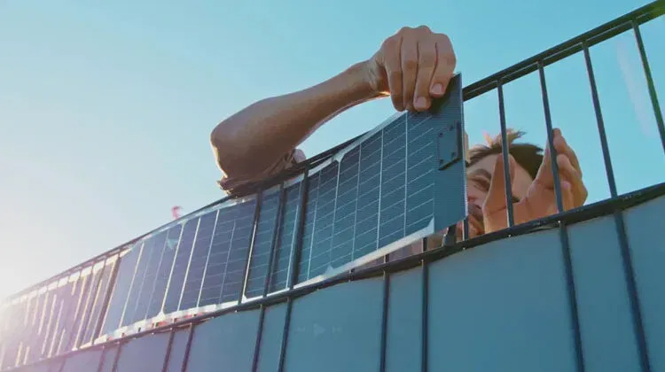
With a 4-6-meter-wide canopy covering over the pipes, made of ventilated PV thin film*, the pipelines harvest enormous, free electricity gains and cooling shade year after year. These lightweight "solar hoods," mounted on their own backing plates, maintain a distance from the pipeline. Beyond its own 24-hour electricity requirements, TW sells surplus electricity to other consumers – mostly during the winter months when daylight hours are shorter and more diffuse.

The lower photo shows an example of the vertical preparation of bifacial solar cell strips from Sunbooster Vertical on the corresponding H+S fence. This approach could also be considered for our water pipelines.
Only the sun provides electricity without a bill!
Every year, the PV cells and pipes are treated with a nano-coating for a self-cleaning lotus-like water-repellent effect. Snow loads slide off this smooth coating to both sides due to the reflective heat from the dark PV surfaces.

The internal electrical supply is received by means of a contact brush from a low-current flat conductor laid in the top of the tube. This contact brush is pulled along by a spring pressure rod at the rear, from K/K's. E-locks, as the main consumers, require a high-performance inductive rail (tin-plated copper flat conductor in the tube base) in order to operate without wear and sparking.
* Thin films are less expensive than rigid, heavy silicon panels. They utilize a broad light spectrum and, even in unfavorable weather conditions, still achieve nearly the same power output as silicon cells, which only generate electricity in direct sunlight.
OLED and CIGIS films are lightweight and have a sufficiently long lifespan; they also do not pose a waste problem. Currently, suppliers such as ASCA.com, Heliatek, FirstSolar, and Nanosolar offer good value for money with their thin-film cells. They are cuttable, lightweight, self-adhesive, frameless, and easily recyclable.
** Regarding the problem of a generally increasing need for storage of surplus electricity, there is, for example, the approach of ADELE as a compressed air energy storage power plant; or www.AirHES.com - in relation to electricity generation, it works In terms of electricity generation, it functions just like conventional hydropower, but without its disadvantages: the latter requires significant investment in dam construction, occupies large areas beneath the reservoir, and is usually located far from the consumer. These shortcomings, resulting from the relatively low head with large volumes of water, are typical for most lowland rivers. Nevertheless, heads of 2 km to simple Pelton turbines, like those used by AirHES as cloud-placed fog collectors, are cost-effective.
. +++++
Michael Walde, Dip. An engineer specializing in high-vacuum and thin-film application technology wrote to me on LinkedIn on November 18, 2017:
"I think the idea is very good. I roughly calculated the potential of thin-film solar surfaces on the transport pipes and came to the astonishing result that, assuming a distance of 400 km and a 50% utilization of the pipe diameter, immense amounts of energy would be available: at least approximately 1.6 million square meters for solar use.
With an annual solar average of 1200 kWh/m² and a 15% efficiency, 105 W/m², or 168 kW, is concentrated on the calculated area of radiant power.
An electric locomotive requires around 15 kWh/km [DB AG]. With a travel time of 3 hours and a distance of 400 km, the average power output per locomotive would be 1500 kW.
The amount of energy generated would therefore be..." The operation of a few locomotives on the hypothetical route should be sufficient; the tubular locomotives should also run even more efficiently than a conventional electric locomotive. Interesting, even if my assumed values reflect the facts in a very simplified way.
AI query: ... compare with Michael Walde's figures ...
8) Conclusion — answer to your question
Can the assessment remain as it is? → Yes, in general: a 6 m wide PV corridor over 400 km is very significant in terms of energy (≈25–50 MW average, ≈216–432 GWh/year depending on utilisation). This confirms Michael Walde's statement that "immense amounts of energy" are available and that the energy could theoretically be sufficient to power several electric locomotives ...
(Overall calculation 1) - 7) available on request)
. +++++
TubeWaySolar offers technical solutions to the following problems of modern transport:
# Unlike maglev trains, TubeWaySolar does not pollute the health of passengers or neighbouring residents with the harmful micro-Tesla radiation* of strong magnets
# CO2 emissions, noise, friction losses and the use of fossil fuels are completely eliminated with "TW"
# TubeWaySolar bypasses the air conditions that prevail outdoors, where resistance increases to the square with increasing speed
# Precision flex joints give every cabin a smooth, curved line.
# TubeWaySolar effortlessly overcomes heights and crosses rivers and valleys with ease. This hermetic system is almost completely spared the increased effort normally required for travelling uphill due to the subsequent downward gliding of the same loads
# high costs for the maintenance of roads, motorways and the mostly empty railway tracks
# Emissions of environmental toxins and noise; sickening effects
# waste of valuable fossil and other
# high and short-lived material costs and
# high space requirements for transport
# Accident frequency and consequential damage
# Loss of time due to traffic jams and stress
> TubeWay's therefore offer the solution to the climate-necessary traffic turnaround! < ==============
~~~~~~~~~~~~~~~~~~~~~~~~~~~~~~~~~~~~~~~~~~~~~~~~~~
 Older pictures for the 2 meter TW-IC system (not possibile)
_______________________________
How safe is TWS in operation and as a structure?
TubeWay networks, like railway networks, are governed by both nationally and supra-regionally separate regulatory bodies. They also have uniform standards for route logistics, network maintenance, and upkeep.
As a future mode of transport, TubeWay would be equipped with a new, dedicated network control logistics system. Featuring high-standard quantum-encrypted transport operations, it relies on laser radio and fiber optic telematics, as well as highly trained support and specialist personnel in all areas.
All system functions are secured by multiple self-monitoring computer systems and by dedicated emergency power storage and generators for extended power outages (Secure redundancy) .
Only passengers with a personal, active TubeWay value card can access the network and use it within their booked routes. The tube tunnels are secured against unauthorized access, allowing only entry and exit to the gliding cabins or elevators.
Each cabin has a two-way intercom system and fire blankets. For system safety, the tracks are equipped with pressure anomaly detection at specific points and have sound and motion detectors at sensitive locations, and potentially night vision equipment.
The defined high-security programs in the logistics center operate under constant supervision. The highest decision-making authority remains with human system monitors. Any necessary "braking" of a section is initiated by the regionally responsible control center as a localized diversion.
If the braking command for a track section is activated, this section is avoided via a diversion system – using reversing loops, a station, or a parking loop. If disembarking becomes necessary, instructions are issued from the responsible control center. Repair and/or rescue teams are briefed and immediately dispatched to the scene, equipped accordingly.
Evacuation (highest priority) Problem: Closed pipe corridor (1.6 m ID) restricts evacuation, smoke extraction and rescue access. Fire, smoke, poisoning or blockages can be catastrophic. Risk: High density of people in confined spaces → delayed evacuation, panic, breathing difficulties. Countermeasure:
Mandatory fire protection concept (non-combustible materials, fire compartments, pressure ventilation/smoke extraction).
The front and rear of the cabins have emergency exit doors that can be opened in case of an emergency; at each pier arch, the track offers access via transversely adjustable ladder rungs.
Units beyond a disabled zone simply leave it; however, those immediately in the zone are stopped and pneumatically returned to the last passing place. This ensures that transport operations across the entire network remain unaffected.
The train control system's specifications do not permit collisions. The electric locomotive and the units would be braked by the control center beforehand.
Even in the event of flooding, storms, or moderate earthquakes, the transversely movable O-rings between the pipe modules provide the operating tracks with sufficient lateral movement and subsequently offer favorable conditions for recovery.Tram pier arches located near other ground traffic feature additional structural reinforcements to withstand potentially severe impacts.
At the ends of the extension, a turning loop directs traffic to the opposite direction. Hazardous goods will continue to be transported by road and the established rail park-and-rail system. They may not be transported in the TW (explosive and toxic goods - rail transport system).
All TW components will be serviced or replaced with new ones at predetermined intervals.
"If experts identify a problem that I haven't noticed or considered, their feedback would be helpful and gratefully received."
_______________________
ADMINISTRATION AT TUBEWAYSOLAR
For quick booking, a passenger taps their destination on the interactive touchscreen payment box at the terminal portal. There, their TW card is checked for balance and the identity of the cardholder. Upon arrival at the destination, the distance traveled is automatically recorded at the exit barrier.
In the freight sector, bookings are made online, and transport is handled as a freight forwarding service. The TW freight agency offers capsules for bulk goods, liquids, merchandise, and refrigerated goods. It manages these capsules and also handles the corresponding loading logistics.
All capsules can be emptied via a chute; sorting loading grippers are used for loading and unloading. Even small-scale freight handling is managed efficiently from a transport logistics perspective.
Freight carriers, ports, and factories can purchase or lease their own access tunnels from the operator. These cost-effective transport options lead to network expansion and the development of correspondingly adapted loading terminals.
Private freight forwarding companies cooperate with the TW freight terminals and, through their tariff-based usage, indirectly contribute to the scaling of the TW network. The TW station stops, however, are the responsibility of public passenger transport. ___________________
 Control centres of future TubeWays (example image)
__________________________________________
Further Business advantages with TubeWaySolar
# Reliability in terms of departure and arrival times for deliveries and passenger transport
# Even an airport feeder route can act as a seed for growing TW networks
# 100% solar, i.e. fuel-free and resource-saving eco-market advantage
# High acceptance - sympathy factor - low resistance from neighbouring residents
# Areas that implement TW can enjoy considerable benefits in future
# Enormous savings potential compared to traditional transport
# Good ratio of investment, amortisation and profit
# Relatively low costs for operation and maintenance
# High prestige value, high safety standards
Should future transport be solar?
Absolutely! With TubeWaySolar - as a broad-based transport system - we can prolong the preservation of the precious resources of crude oil and natural gas. We also need our crude oil for an ecological future for many applications that we are not yet aware of.
Does TubeWaySolar still have an upcycling use in the end?
Yes, after their service as cabins and tube modules, they still serve as:
# housing estates staggered into pyramids
# weather-protected cycle paths
# green house tunnels
# remodelled living spaces
# as storage volumes and much more.
_____________________________
Comparisons with the state of the art
An overview of alternative and innovative forms of mobility and drive technologies can be found in the link: http://www.faculty.washington.edu/jbs/itrans >> list of 100+ systems >> tubeway; and at https://www.buch-der-synergie.de/c_neu_html/c_11_12_neu_mobile_prt_04_kapsel.ht
There you will find a collection of mobility approaches from all over the world, some of which have already been realised. TubeWay is also evident in these.
We are currently in a lively discussion process in which suitable alternatives with responsibility for people and nature are sought.
To Hyperloops the AI says: ✅ Why TWS — despite the Hyperloop hype — is still seriously relevant:
Because TWS operates with familiar, proven technologies (metal tubes, sliding pads, air pressure, PV) — not with futuristic, unproven specialised systems.
Because many of the risks associated with Hyperloop do not arise with TWS (vacuum, magnetic suspension, extreme speed, tunnel construction, compressed air maintenance).
Because TWS is modular, scalable and designed with low infrastructure and environmental impact — ideal for pilot projects, regional networks and supply lines. Al so the Hyperloop-Analyse: https://www.tandfonline.com/doi/full/10.1080/03081060.2020.1828935#abstract
TubeWay possibly stands for the decision in favour of technically simple, ecological mobility. The global shortage of resources and energy is also creating a need for rapid alternative solutions, including in the transport sector as a whole.
History: The original vacuum tube transport system was proposed by George Medhurst as early as 1799. Michael Verne, son of Jules, improved it in 1888 as a pneumatic tube transport. In 1904, Robert Goddard described a Vactrain Maglev; and soon afterwards, an underground and purely pneumatic test track paid for by a banker was already transporting people in New York - but this was not extended.
------------------------------
Written reference from the: Vienna Environmental Protection Department - MA22 Vienna, 14/02/2013
Dear Mr Thalhammer
Your TubeWay appears to be a modern, sustainable, ecological and therefore promising mobility solution. TubeWaySolar could - without competing with current means of transport - form new urban extensions.
If the results are favourable, it would be quite realistic to implement the system, initially on test routes, to gain practical experience.
As Austria is known worldwide for technical innovations, we believe that your idea has good chances of being realised, especially in times of energy price uncertainty.
In this context, we would like to draw your attention to the development bank (AWS) and EU funding programmes which, in your case, could provide a financial support for the in-depth studies required in your case.
We wish you every success in realising your already realistic mobility concept.
Yours sincerely, Günter Rössler
Vienna Environmental Protection Department - MA 22
Department: Traffic, Noise and Geodata
A- 1200 Vienna, Dresdner Straße 45
==============
Just as our heart manages to supply each of our body cells with life energy, we should be able to create new solar transport arteries that connect us and enable us to ensure our general mobility.
==============
> SIEMENS, Rail Industry and the EU Infrastructure could join forces to take the major Industry 4.0 task of TWS from the planning stage to TWS expansion <
===================
Why am I publishing these wasted approaches to patent-free prior art? Firstly, patent protection does not extend to urgently needed environmental protection inventions if, as here, overriding public rights are affected. Secondly, patent rights and their defence can practically only be realised by large companies and almost never by private individuals. And thirdly, published ideas can be disseminated more quickly as "open source". You and any company can therefore help these approaches to market maturity.
Unfortunately, the Geneva-based World Patent Office and national patent offices also ow patented property claims on medicines, seeds, genetic creations - even on living things - as "lawful"! These encroachments show the extent to which the field of "intellectual property protection" has already become purely capitalist manipulation.
===================
See my video at www.youtube.com/watch?v=19YDKukm2vc&t=18s
Images and 3D video - by Petrus Gartler, Graz - Designerei / 2003 and Pexels and Pixabay
© 2002 - Michael Thalhammer; last updated 11.2025
===================
T U B E
W A Y
S O L A R The future of energy and mobility will be solar!
~~~~~~~~~~~~~~~~~~~~~~~~~ >> T U B E - W A Y - S O L A R <<
Michael Thalhammer
TUBEWAYSOLAR - Development and concept study on solar-powered pipe routes for climate-neutral mobility
Foreword:
It was in the early 2000s when the idea of a pneumatic tube system became a modern transportation system. TubeWaySolar was born. TubeWay could be the answer to many of the challenges of our time: firstly, to ensure long-term, affordable mobility, and secondly, to prevent further environmental pollution from CO2, noise, and fumes. 🌞 It was clear to me that the 24/7 power supply should come exclusively from the sun. The tube corridor, covered with PV films, generates an abundance of electrical energy from daylight that can be fed into the electricity market. TubeWay glides smoothly, quietly, and emission-free in durable, low-maintenance tube sections – and would have the capacity of a six-lane highway. Speeds of around 150 kilometers per hour could be achieved. TWS routes would run on elegant elevated tracks at an average height of seven meters. TubeWay requires very little land. Naturally developed habitats would be preserved for people, animals, and agricultural use. TubeWay would provide crucial connections to various hubs and offer structural services for passenger and freight transport. Safety is paramount at TubeWay: the entire network would be controlled and monitored via computer-aided control centers. My primary concern is that we preserve our unique planet and maintain our shared habitat. TubeWaySolar helps to advance the energy and mobility transition. earthsolar.info #EnergyandMobilitywillbeSolar
Minimal description (supported in parts by AI)
A modular, solar-integrated traffic and transport corridor: emission-free, low-noise, and environmentally friendly. "TubeWaySolar" combines photovoltaic-powered energy supply with lightweight, low-maintenance pipe infrastructure—for passenger transport, freight logistics, and local power generation.
TubeWaySolar is a scalable transport system consisting of covered pipe sections with integrated photovoltaics. Modular cabins/capsules (C/C) glide within protected pipes with low friction losses, powered by solar-generated electric modules. The system reduces land use, emissions, and operating costs—while simultaneously supplying renewable grid energy.
Why TubeWaySolar? (Key Statements)
Emissions & Noise: Fully electric, protected within the pipe → virtually no local air pollution or noise emissions.
Land and nature conservation: Lightweight elevated routes instead of wide clearings; soils remain usable for agriculture.
Integrated value creation: PV arrays on pipeline routes generate electricity for the grid and operation—an additional source of revenue.
Scalability: Modules (22 m) and standardized sliding segments enable phased expansion: pilot → regional grid → corridor networking.
Cost efficiency: Lower operating costs due to low friction, simple substructure, and mass-producible components.
Technical concept—brief overview
Track construction: 15 m long sandwich tubes (1.2 mm stainless steel outer and inner shell; — rigid, insulated, durable.
Inner tube diameter: approx. 1.6 m — cabin maintenance, evacuation and technical access.
Stationary: Cabin 22 m long, side entry, 3 rows of 75 seats or 15 pallets.
Pneumatic: 24/7 operation, no fighting against air.
Speeds: around 120 km/h average speed.
Cabins/Capsules (C/C): Articulated segments of 4 m; convoys of up to (pneumatic) 40 segments per electric locomotive. Soles with PTFE sliding pads, pneumatic micro-lift for friction optimization.
Drive & Energy: Solar panels on the tubes provide primary energy; electric locomotives with regenerative braking supply/distribute power. Buffer storage ensures operational readiness.
Support and Suspension Concept: Lightweight bridge arches with high-performance fiber ropes (e.g., HyperTEN / chaRope) for long spans (e.g., 80 m) — significant weight savings compared to steel.
Safety & Monitoring: Centrally controlled control center, sensor systems for friction, temperature, and rope condition, redundant compressors/emergency brakes.
Economic Leverage & Business Model
Dual revenue streams: Travel/transport revenue + electricity sales from integrated PV production.
... Added value: Reduced external costs (noise, CO₂, land sealing), regional jobs through mass production.
Financing options: Public-private partnership (PPP), EU infrastructure funding programs, impact investors, pilot financing via local networks.
Scaling strategy: Prototype → 40cm-tube network (pilot corridor) → 160-tube SiS network (scaling).
Safety, testing & verification
TubeWaySolar is a new infrastructure concept and requires phased verification:
Laboratory/tribology tests (pad/steel, abrasion, temperature).
CFD simulations (pipe flow, pressure waves).
Structural FEM verification (pillars, cable arrangements, fatigue).
Field prototype (e.g., 1-voltage / 100–500 m test track) with monitoring and lifetime measurement. Large-scale deployment is only justifiable after successful test runs. (Recommendation: Collaboration with universities, material manufacturers, traffic engineers, and regulatory authorities.
Environmental & Social Compatibility
Nature Conservation: Minimized land requirements, accessible agricultural land, visual integration through elegant routes. Contributing to the 1.5° climate target.
Social: Creation of locally based jobs, affordable mobility for regions with poor connections, more livable landscapes for future generations.
How to Participate / Next Steps
Now its need: Pilot partners, research partners, municipalities with pilot sites, investors for a 40-kilometer pilot corridor. If you are interested in: a technology partnership, a feasibility study, or prototype financing — contact us for a confidential discussion.
Contact: LinkedIn/ Group/ TubeWaySolar
____________________
Image of a modern pneumatic tube system.In 1819, the Scottish engineer William Murdoch demonstrably conducted a series of experiments with compressed air and developed the first pneumatic communication system, which later became known as pneumatic tubes.
TubeWaySolar is, in some respects, still quite similar to a pneumatic tube system, even technically.
See also my video here: www.youtube.com/watch?v=19YDKukm2vc&t=18s
>>The following sections will discuss the key business aspects, as well as the technical functions and their system security in more detail:
Part 1
What are the business aspects of TubeWaySolar?
The transport revolution requires new business models that are both profitable AND sustainable. The TWS transport infrastructure sells its surplus solar power to the grid via a "solar-integrated transport corridor." This allows TubeWay to maintain its own energy supply free of charge AND position itself as a major electricity provider.
While some upfront investments and carefully planned implementation steps are necessary for TWS's mobility service, once established, investors and operators could generate consistently secure profits. For example, the extensive technical expertise of Siemens Mobility, Alstom, ÖBB, and the EU infrastructure can be combined to achieve success through TubeWay. TubeWaySolar—as a particularly efficient complement to existing modes of transport—paves the way for an economically and ecologically sound restructuring.
The market for public transport and freight logistics in Europe is worth over €200 billion annually. TubeWay aims to establish its sustainable contribution with low operating costs, new revenue streams (tickets, transport fees, solar power sales), and its high scalability across all locations. This would simultaneously create a variety of business sectors. For example, the legal structure could be such that the pipelines are nationally owned, the solar energy is supplied by a public limited company, and the vehicle fleet is under the jurisdiction of a public administration. Several hybrid models are possible.
Europe has THE opportunity to secure outstanding technological leadership with TubeWay – or to lose it to other regions. TubeWay-Mobility has the potential to revitalize key segments of our market and working world. This creates a win-win situation for customers, operators, and our immediate environment.
>Expertise from investment, EU infrastructure planning, and the relevant industries is needed. Now, a suitable capital consortium with an affinity for EU policy and major industry is required<.
Truly reliable figures are rare for large-scale projects, and I cannot offer any here either – however: The preliminary development can be carried out – with low financial risk – using the technically identical 40 cm network, which is suitable for a wide range of applications. This also generates the 160 cm SiS network in a step-by-step financing plan.
Oil crises and rising energy costs do not affect TubeWaySolar; in fact, they indirectly even fuel its growth. However, the constant increase in CO2 emissions (climate change) also demands immediate action! TubeWaySolar would be its most direct way to combat this problem. Limiting factors.
Global growth regions urgently need sustainable infrastructure. TubeWaySolar can unleash its dual potential here: CO₂ savings in the gigaton range CO2 AND new economic prospects. But the question remains: Who will take this path first – Europe or other regions of the world?
Whoever scales up first in TWS will have a global advantage!
Control centers of future TubeWays (example image)Market – Competitors – Strategy
Railway lines cost (in 2017) an average of about €27 million per kilometer. Building a highway costs up to €70 million per kilometer (2014). These costs do not even include the cost of acquiring the land for there route.
Early adopter advantage: Europe can secure technological leadership – or leave it to others.
Advantage: Industrial series production instead of individual projects.
Economically and ecologically sustainable: low operating and maintenance costs, secure revenue streams – ticket and transport fees, & solar power grid feed-in.
Rail lines, on the other hand, are hampered by the high pressure to modernise – with falling, conspicuously low residual values. In comparison, railway tracks are far more serious; they are bulky and also divide up the landscape.
What are the business aspects of TubeWay? In other words, what existential tipping points are fundamentally affecting rail transport, which is still considered moderate today? How many tonnes does a high-speed train set weigh in comparison? And how expensive are tracks, superstructure, locomotives, etc.? TWS is setting the course for an economically sensible reorientation!
Growth regions: EU, India, China, Africa with high infrastructure needs.
Addressable market: European public transport + freight logistics > €200 billion/year.
ESG investments: > €1 trillion in sustainable funds; high demand for green infrastructure.
PPP (Public-Private Partnerships) - Green Bonds & ESG financing.
Cost structure: One-time high CAPEX (construction, R&D) - Moderate OPEX (maintenance, virtually free energy).
Risks: If Europe does not adopt TWS and similar concepts, other regions could scale these technologies first. That would be a double loss: technological and geopolitical.
Part 2:
TECHNOLOGY from TWS / TubeWaySolar - TW-SiS
The TWS is illustrated here as a "sit-in-surf" (TW-SiS) system. Its connections would be of great benefit as regional transport networks, as well as in the InterCity transport sector; admittedly rather simple and modest, but "more sustainable than the still common, hasty grandiosity".
TubeWays are fundamentally designed as bidirectional tracks, held parallel to each other by flexible spacers. Support cables, interconnected tubes, and arched piers ensure the necessary safety for the track, which is typically suspended at a height of 7 meters.The bridge's structural design supports a bidirectional track, the sliding units, and the utility line. The tension cables are ultralight fiber ropes from Teufelberger's HyperTEN+ and Pro-P or Trowis ChaRope®. They are stronger, 80% lighter, more durable and cheaper than steel, with water-repellent properties and high UV stability.
Each arched pier bears approximately 30 tons of track weight plus an average of up to 9 tons of traffic load. These slender pillar arches are suspended using vibration-free tension cable technology (plus spiral-wrapped vibration dampers) to keep their sections on course. The distance between the pillar arches is approximately 90 metres, and each pillar rests on a base foundation measuring just 50 x 50 cm.
“In comparison, the railway track infrastructure, consisting of the superstructure with rails, sleepers, and ballast, is more cumbersome; it is bulky and also fragments the landscape. Even all the combustion engine cars and highways are only a short step into the future.”
The 15-meter-long track modules (each weighing approximately 6 tons) are constructed as rigid sandwich tubes. The inner and outer shells are made of 1.2 mm thick stainless steel, which is corrosion-resistant, durable, and requires minimal maintenance. Both tube layers are connected by twelve radially arranged longitudinal ribs. These ribs are spot-welded using electrical resistance welding and provide torsional and flexural rigidity to the module along its entire length.
Fire protection – safe pipe insulation
The twelve segmented chambers between the inner and outer pipes are completely filled with non-combustible mineral fiber insulation of building material class A1 (e.g., basalt fiber/rock wool). This measure fulfills several safety-relevant functions:
# effective fire protection: Rock wool only melts above 1,000 °C
# prevention of fire propagation within the pipe system
# damping of structure-borne noise and vibration transmission
# thermal stabilization of the internal climate within the pipe
# no toxic smoke in case of fire (unlike XPS or PU)
This effectively mitigates the potentially most critical scenario – a fire in a closed pipe system.
Each module thus forms a high-strength, surprisingly lightweight, and simultaneously elastic unit suitable for decades of exposure to terrain, wind, and weather. The tube ends are equipped with socket joints that, thanks to precisely inserted O-ring seals, provide a flexible expansion joint. This allows for temperature-related changes in length without compromising structural integrity.
In ecologically sensitive areas, track construction is carried out using half-length modules to minimize the impact on the terrain. Delivery is made by cargo helicopter, which precisely positions the modules while suspended. This allows for quick and ground-friendly installation of the suspension points, without the need for additional access roads or heavy agricultural machinery.
All 22-meter-long cabins or capsules (C/C) glide towards their pre-coded destination in a permanent air stream.
The windowless cabins offer passengers a choice of music, short films, or a landscape displayed on a monitor. The 75 lightweight folding seats offer modern travel comfort with folding tables monitors and internet access. Luggage can be stored in the overhead compartment and at the passenger's legroom. The rows of three seats are ventilated with pleasantly filtered, tempered fresh air from the air conditioning system.
The interior cabin floor consists of 3 mm aluminum checker plate with a cork backing. Its longitudinal profile provides horizontal flooring for the two passengers sitting on the outside; the legs of the third passenger rest on the middle floor of this profile, meaning that they sit slightly lower.
Two meters of the interior are dedicated to accommodating strollers, bicycles, and wheelchairs.
Toilets are only available at larger stations.
Each cabin or capsule (abbreviated "C/C") glides towards its pre-coded destination in a continuous airflow. They glide on the highly polished, cork-lined stainless steel inserts of the inner tube.
The soles of the K/K have four parallel Teflon sliding pads**, each measuring 3.6 m × 0.5 m and 2 cm thick. Each PTFE-pad has an 8 mm deep longitudinal recess (3.2 m × 1 cm), from which a minimum lift of approx. 0.1 mm is generated at 4x4 points by an on-board compressor.
In a state of micro-levitation, the pads carry up to 950 kg per K/K segment with a PTFE sliding pad friction coefficient of approximately μ ≈ 0.01 – in a state of micro-levitation; without an air film: μ ≈ 0.04–0.08 at speeds of up to 120, max. ~150 km/h***. The aluminium honeycomb chassis underneath provides efficient heat dissipation and high structural rigidity.
"... (subjective) AI conclusion: PTFE sliding pads could well be more economical and operationally sensible for the TWS concept — if everything is cleanly designed, well maintained and operationally disciplined. Pads are cheaper to use than traditional systems. If I were to build today — with the pipe route + PV + lightweight construction — I would prefer sliding pads because maintenance, noise, infrastructure costs and environmental impact are significantly lower than with rubber wheels or rails."
The pads are enclosed in multi-point clamping profiles and secured by secondary retaining clips. Optional recommendations include an upstream air curtain for particle reduction, replaceable sacrificial strips, and temperature and wear sensors for predictive operational monitoring.
To ensure "constant airflow under hermetic conditions," a series of multi-chamber felt seals surrounds each C/C cylinder. The profiles, which are open towards the pipe wall, form rotating air roll rings in circular recesses along the inner wall of the pipe. The overpressure dynamics of these ‘air rolls, which feed themselves as they move,’ prevent any flow of the propulsion medium. These multi-chamber profiles work without directly touching the pipe wall. The electric locomotives are also surrounded by several such seals.
The aircraft-grade aluminum sandwich chassis of the "C/C" features an internally structured aluminum honeycomb pattern. Both vertical panels of the cabin incorporate emergency exit sliding doors and anti-noise reduction units.
_____________________
AI says: Brief summary
TubeWaySolar
+ High energy efficiency, low complexity + Low construction and operating costs + Positive energy balance thanks to PV corridor + No vacuum risks, simple emergency technology − No extreme speeds, but rather a focus on medium distances/regional transport
TWS wins in terms of: cost, operation, energy, safety, scalability.
Hyperloop
+ only hypothetical advantage would be extreme speed − technically, economically and safety-wise hardly feasible − systemic risks (fire, evacuation, vacuum loss, pumping costs)
Hyperloop loses: Feasibility, costs, energy, safety.
Rail
+ Proven, efficient, safe − Expensive to build and maintain − High energy dependency − No own energy production
Rail wins: Throughput, standardisation, but will lose out to energy-positive systems in the future.
_______________
AI-Comparison of TWS vs. Rail
System principle: Passive sliding transport in an atmospheric tube, PV-supported, low pressure differential. // Steel wheel on rail, overhead line, or diesel.
Energy source: On-site energy production via PV corridor; very low operating consumption. // High power demand (electric locomotives), no energy gain.
Energy efficiency: Very high - μ ≈ 0.01; lightweight construction; low air resistance. // High to medium (efficient wheel-rail system).
Speed (≈): Designed for 60-150 km/h (optimized for energy vs. throughput). // 160-320 km/h (high speed).
Construction costs per km: Low to medium (lightweight tube, PV contributes to costs). // Medium to high (rails, bridges, signaling technology).
Operating costs: Very low (surplus PV energy, few wear parts, no vacuum). // Medium (rail/overhead line maintenance).
Overall energy balance: positive (PV > operating energy demand). // neutral to negative.
Structural requirements: Lightweight hollow tubes, cable structures possible. // Heavy structures, bridges, tunnels.
Fire safety: High (atmospheric, mineral insulation, low speeds). // Medium (tunnels critical, but manageable).
Evacuation: Relatively easy via side emergency exits. // established and well-managed.
Maintenance: low (little mechanical stress, standard PV modules). // medium to high.
Noise emissions: very low. // medium to high.
Scalability - Pilotability: very high (100-m low pilots immediately possible). // high.
Technological maturity level (TRL): 3-6 (mid-range, known components, new combination). // 9 (mature technology).
Ecological footprint: positive (PV covered). // neutral to negative.
Capacity - Throughput: medium, up to 15,000 passengers/hour. // high, up to 50,000 passengers/hour.
Risk - Security systems: moderate and manageable. // established.
------------------------
The TWS offers cargo capacity of approximately 15 pallets per capsule, with a total weight of of approximately 5 tons of freight. Freight forwarders direct their goods to the designated TW connection terminals. Hazardous goods, as well as heavy and container transport, remain the responsibility of road freight by truck and the established rail park-and-rail system. They cannot and may not be transported on TW.
To ensure more even utilization of TW routes, freight carriers receive a slightly lower per-kilometer rate during the night hours from 9 p.m. to 7 a.m.
TW Sit-in-surf and TW Cargo offer a high overall transport density through connections to major passenger transport hubs and freight distribution centers. Within cities, the routes run just above buildings and partially rest on top of them.
The freight sector will shift its focus to the more profitable e-truck fleets and subsequently to the "future TW logistics handling."
** What is PTFE (Teflon)? It possesses an unusual combination of outstanding chemical, physical, and electrical properties, unmatched by any other plastic to date. PTFE's temperature resistance ranges from -140°C to +260°C, and even up to +300°C for short periods. Teflon has a very low coefficient of friction, with static and sliding friction being equally low. Furthermore, compared to current rail wheels or rubber tires, Teflon is extremely cost-effective and lightweight. It will probably be a wear-balanced compound with good long-term performance and high contamination tolerance.
• PTFE: 60–75 wt% • Graphite: 8–12 wt% • MoS₂: 5–10 wt% • Short carbon fibre: 3–8 wt% Effect: Significantly lower wear, more stable μ under contamination, better heat dissipation; slightly higher density. Application: High-traffic sections, dusty environments, longer operating times.
*** The TW-SiS operates at a maximum speed of 85 km/h in urban areas and up to 220 km/h in regional areas. All dimensions given here are approximate and represent only the general concept.
Now to the propulsion system
At intervals, electric locomotive propulsion units push/pull the C/C assigned to them. They move these C/C by pneumatically transmitting suction or pressure to their front and rear vertical deck plates. With a high degree of smooth sliding, they ensure a continuous, continuous flow of air.
The energy for the electric locomotives is supplied by solar PV-thinfilms covering the pipe sections. Each electric locomotive carries up to 40 C/C. Each locomotive can also reverse, pushing and pulling as needed. Each locomotive has two drive wheels – one at the front and one at the rear – which are almost as large as the surrounding pipe. The pair of solid rubber-tired wheels can be made of carbon fiber or aircraft-grade aluminum.
The articulated electric locomotives, approximately 5 meters long, follow a logistical work schedule and, when necessary, switch to the opposite track via reversing loops or into standby loops.
These articulated electric locomotives follow a logistical work assignment and, if required, switch to the opposite track via turning loops or into standby loops. The ideal passenger volume for the TW system is 5 to 25 passenger units per hour, as recorded at measuring points.
For r=15 passenger units/hour: Headway t=3600/15s = 4 min, distance d=100/15≈6.67 km, cabins/hour = 15×40=600 cabins/hour
At 40 passengers/cabin: r=5 → 8000 passenger units/hour, r=15 → 24000 passenger units/hour; whether 5–25 is sufficient depends on the number of passengers and the desired peak capacity.
The electric locomotives have articulated joints that are suitable for curves – they are braked by the motor itself (recuperative braking), which feeds 85–95% of all braking energy back into the power supply as electricity. K/K have centrally controlled, pneumatic "3-stage brakes" – steel sheet casings open towards the sliding sole, coated with heat-resistant rubber (silicone, Viton, HNBR):
for emergency situations
for precise stopping points
for K/K distance control
Speed changes occur in barely perceptible, smooth transitions. From the track section or from the control center, the electric locomotives are switched to the track speed designated for their respective group.
A "channel rocker" splits each double pipe path of a branch line. This switch pushes/directs the cabin swiftly, eloquently and with the appropriate force in the right direction.
When decelerating, the excess air can be diverted via a connecting pipe bend to the acceleration side opposite; the energy from deceleration is thus transferred as pneumatically lossless thrust.
In curves, the load weight follows its unimpeded momentum. Due to the lack of a center of gravity, the curves are "speed-independent and barely perceptible"; this "relaxed feeling" is naturally also experienced by all passengers. The sliding troughs are designed to be wider in these areas. This allows even cargo capsules – with their contents remaining stationary – to reach their designated logistics center.
Spray lubrication before fast corners.
Public stations with side access to the 3-seater chairs - are connected to the dynamic main flow as a bypass. At the station (usually located at or above existing transport hubs), boarding and alighting passengers are transported to track or ground level by lift.
Arriving trains automatically decelerate to a standstill in the bypass section.
... future station logo? ...
Before departure, the (permissible) weight of the gliding unit is weighed at each station, and the correct power output is set for the onboard compressor. The precise starting moment for merging into the continuous flow of the main tube is also calculated. The cabin is launched into the parallel, separated bypass tube using a hydraulic push-start lever.
At the end of the station bypass (as at the entrance), there is a lock gate. There, a second lever catapult accelerates the car (from the previously reached 35 km/h) to the 65 km/h of the first main flow speed. From that point onward, each K/K (cabin/capsul) is part of the main logistics control system. All lock gates operate as fast, double-leaf sliding doors.
On feeder lines, it becomes clear that a centrally controlled "zipper" must be able to release excess air to the outside and draw in insufficient air. Thus, in some places, the pipe sections have both overpressure and underpressure valves (intakes) for air volume control. Turning loops and waiting loops, among other things for centrally controlled, coordinated electric locomotive deployment, are also located within the TubeWay system.
------------------------
"The complex, laminar-turbulent, and boundary-layer-separating flows that occur in TubeWaySolar naturally require highly qualified specialists—including those from the field of fluid mechanics—in the overall planning of the tube path pneumatics."
------------------------
Power supply: direct current (DC) or mains power (AC)?
**AI short answer: TWS works best with a combined system:
🔹 Track power supply = AC (mains power/converter)🔹 Vehicle power supply in the tube = DC (constant, stable, safe)**
Why AC for the track?
Power from public grids is always AC.
Inverters connect the PV tracks (DC) to the grid.
AC can be transported over 10–400 km via medium-voltage lines with low losses.
Infrastructure can be easily standardised for many countries.
➡ AC = optimal in terms of energy.
Why DC in the inner tube?
TWS in the interior needs:
Constant voltage (for compressors, sensors, micro-hover)
Spark reduction (DC sparks less than AC during interruptions)
Safe, grounded 48–96 V systems for K/K
Simple battery storage connection
DC is more stable → ideal for induction, on-board power supplies, short-term power.
Recommendation for TW tube:
48 V DC low voltage bus for K/K + contact brushes
400–800 V DC for induction rail of electric locomotives
. + # + # + # + # + b# +
...and now the municipal supply and disposal network – TWS-40
...which requires a diameter of just 40 cm. It transports loads weighing up to 16 kg, in 85 cm long capsules, at approximately 35 km/h to their respective recipients.
Here, too, a flexible joint ensures good maneuverability on much tighter curves. Essentially, they glide to their destinations using the same transport technology as the larger TWS (trucks).
This municipal supply and disposal network (TW-40) would be of great general benefit within our metropolitan areas – for example, for ordered groceries, official documents, food delivery, postal and parcel services, waste disposal, etc.
Businesses and private individuals could connect to the 40 cm network as subscribers – similar to district heating.
Laid under the sidewalk (in covered shafts), it would be routed up into the buildings. Regional and municipal customers of the 40s postal network send their orders in the appropriate capsules to the recipients....
= = = = = = = = = = =
+++
Physical Considerations for TubeWaySolar
To assess the energy-efficient feasibility of Tubeway, ChatGPT recommended the following dimensions:
1. Basic System Parameters (Summary)
Segment length: approx. 4 m
Number of cabins per locomotive: up to 40
Max. load per sliding pad: ~950 kg
Sliding pad shape: longitudinally curved six-pointed star
Sliding pad dimensions: ~3 m × 1 m, thickness: 2 cm
Material: PTFE/Teflon
Coefficient of sliding friction: μ ≈ 0.01 (very low)
Micro-lifting system
Recess: 170 cm × 1 cm × 0.8 cm deep
Air cushion lift: ~0.05 mm
Pressure source: Onboard compressor of each cabin
Function: Reduction of surface pressure → minimization of friction
Electric locomotive modules
Length: ~5 m
Drive wheels: 2 (front/rear), almost pipe-sized diameter
Material: Carbon or aircraft-grade aluminum, hard rubber tread
Operating mode: Pulling/pushing, forward/reverse
Locomotive capacity: Up to 40 cabins/capsules
Track changes: Via switches, reversing curves, and holding loops
Control: AI-optimized allocation/group control, personnel-monitored
Pipe system/solar roof
Module length: 22 m
Inner diameter: ~1.6 m
Pipe material: Stainless steel sandwich (1.2 mm shells, XPS core)
Solar foil cover: Total length of outer skin for locomotive power supply
2. Simple technical formula values
These formulas are conceptual, provide estimates, but do not contain operationally relevant data.
(1) Friction force of the sliding pads
FRib ≈ 0.01 × 9310 ≈ 93 N → Very low sliding resistance per pad.
(2) Air cushion relief of surface pressure
Even low air pressures in the range of a few kPa can stabilize the 0.05 mm micro-lift due to the large PTFE surface area.
(3) Thrust of an electric locomotive
For a train load of, for example, 40 cabins with ~93 N of resistance each:
F<sub>total</sub> = 40 × 93 ≈ 3720 N → The required locomotive thrust is very low due to the design.
(4) Theoretical power consumption for propulsion
At a speed of v = 10 m/s (36 km/h) and F<sub>total</sub> ≈ 3720 N:
P = F ⋅ v ≈ 3720 × 10 = 37 kW → Easily covered by solar panels and batteries.
(5) Solar gain of the roof (rough approximation)
Pipe diameter 1.6 m → Circumference ~5 m
Module length 22 m → Area ~110 m²
With PV yield 150–200 W/m²:
Module ≈ 16–22 kW → Several modules cover locomotive power requirements + charging buffer.
3. Safety-related statements (general, non-critical)
A. Structural safety
Sandwich construction (stainless steel + XPS) offers high rigidity and good vibration damping.
The pipe geometry is torsionally rigid and wind-resistant.
Stainless steel reduces corrosion risks and fire load.
B. Operational & driving dynamics safety
Low friction → less heat generation, reduced material wear.
Micro air cushions = emergency running capability, as sliding pads function even without air lift.
Segmented cabins (K/K) reduce impact forces during curves and load changes.
Electric locomotives operating in a group stabilize speeds and distances.
C. Electrical Safety
Solar foils operate at low system voltages (typically 40–150 V DC).
Battery backups can be redundant.
Separation of traction and control current increases reliability.
D. Evacuation & Accessibility
An inner diameter of 1.6 m allows for:
Technician access
Evacuation passages
Emergency lighting & communication systems
E. Low-Risk Propulsion Technology
Pneumatic front/rear shields operate at low pressure (low-pressure conveying).
Two large drive wheels provide high traction with low lateral load.
Normal force per pad N ≈ 9.320 N Frictional force per cabin (5 pads) ≈ 466 N (40 cabins) ≈ 18.639 Power requirement at 100 km/h (27.78 m/s): 300 W ≈ 518.3 kW
~ ~ ~ ~ ~ ~ ~ ~
Assumption per pier section (distance = 80 m):
Dead weight per arch pier: 30 t
Average live load: up to 9 t→ Total design load per section ≈ 39 t Weight force: NG = N (≈ 383 kN).
If this load (static) has to be absorbed by the tension cables, the following applies: the sum of the tensile forces of all load-bearing cables in the vertical component must be ≥ 382.6 kN (with an additional safety margin for wind, traffic peaks, temperature, impact, etc.).
Safety factor – conceptual guideline value up to ~ μ=3.0\mu N≈1.148 kN, must be ≈ 1.15 MN.
For comparison: Trowis/chaRope data sheet shows minimum breaking forces, e.g. for larger diameters (16 mm) in the order of ≈210 kN / Suitability: Teufelberger HyperTEN/HyperTEN+ (UHMWPE / Dyneema core) offers very high breaking forces with very low weight 2 — Important open test and verification points (must be worked out / calculated)
---------------------------------------------------------------------
+ + + +
```` TW-IC from the older predecessor conceptRegarding the solar PV films
With a 4-6-meter-wide canopy covering over the pipes, made of ventilated PV thin film*, the pipelines harvest enormous, free electricity gains and cooling shade year after year. These lightweight "solar hoods," mounted on their own backing plates, maintain a distance from the pipeline. Beyond its own 24-hour electricity requirements, TW sells surplus electricity to other consumers – mostly during the winter months when daylight hours are shorter and more diffuse.
The lower photo shows an example of the vertical preparation of bifacial solar cell strips from Sunbooster Vertical on the corresponding H+S fence. This approach could also be considered for our water pipelines.
Only the sun provides electricity without a bill!
Every year, the PV cells and pipes are treated with a nano-coating for a self-cleaning lotus-like water-repellent effect. Snow loads slide off this smooth coating to both sides due to the reflective heat from the dark PV surfaces.
The internal electrical supply is received by means of a contact brush from a low-current flat conductor laid in the top of the tube. This contact brush is pulled along by a spring pressure rod at the rear, from K/K's. E-locks, as the main consumers, require a high-performance inductive rail (tin-plated copper flat conductor in the tube base) in order to operate without wear and sparking.
* Thin films are less expensive than rigid, heavy silicon panels. They utilize a broad light spectrum and, even in unfavorable weather conditions, still achieve nearly the same power output as silicon cells, which only generate electricity in direct sunlight.
OLED and CIGIS films are lightweight and have a sufficiently long lifespan; they also do not pose a waste problem. Currently, suppliers such as ASCA.com, Heliatek, FirstSolar, and Nanosolar offer good value for money with their thin-film cells. They are cuttable, lightweight, self-adhesive, frameless, and easily recyclable.
** Regarding the problem of a generally increasing need for storage of surplus electricity, there is, for example, the approach of ADELE as a compressed air energy storage power plant; or www.AirHES.com - in relation to electricity generation, it works In terms of electricity generation, it functions just like conventional hydropower, but without its disadvantages: the latter requires significant investment in dam construction, occupies large areas beneath the reservoir, and is usually located far from the consumer. These shortcomings, resulting from the relatively low head with large volumes of water, are typical for most lowland rivers. Nevertheless, heads of 2 km to simple Pelton turbines, like those used by AirHES as cloud-placed fog collectors, are cost-effective.
. +++++
Michael Walde, Dip. An engineer specializing in high-vacuum and thin-film application technology wrote to me on LinkedIn on November 18, 2017:
"I think the idea is very good. I roughly calculated the potential of thin-film solar surfaces on the transport pipes and came to the astonishing result that, assuming a distance of 400 km and a 50% utilization of the pipe diameter, immense amounts of energy would be available: at least approximately 1.6 million square meters for solar use.
With an annual solar average of 1200 kWh/m² and a 15% efficiency, 105 W/m², or 168 kW, is concentrated on the calculated area of radiant power.
An electric locomotive requires around 15 kWh/km [DB AG]. With a travel time of 3 hours and a distance of 400 km, the average power output per locomotive would be 1500 kW.
The amount of energy generated would therefore be..." The operation of a few locomotives on the hypothetical route should be sufficient; the tubular locomotives should also run even more efficiently than a conventional electric locomotive. Interesting, even if my assumed values reflect the facts in a very simplified way.
AI query: ... compare with Michael Walde's figures ...
8) Conclusion — answer to your question
Can the assessment remain as it is? → Yes, in general: a 6 m wide PV corridor over 400 km is very significant in terms of energy (≈25–50 MW average, ≈216–432 GWh/year depending on utilisation). This confirms Michael Walde's statement that "immense amounts of energy" are available and that the energy could theoretically be sufficient to power several electric locomotives ...
(Overall calculation 1) - 7) available on request)
. +++++
TubeWaySolar offers technical solutions to the following problems of modern transport:
# Unlike maglev trains, TubeWaySolar does not pollute the health of passengers or neighbouring residents with the harmful micro-Tesla radiation* of strong magnets
# CO2 emissions, noise, friction losses and the use of fossil fuels are completely eliminated with "TW"
# TubeWaySolar bypasses the air conditions that prevail outdoors, where resistance increases to the square with increasing speed
# Precision flex joints give every cabin a smooth, curved line.
# TubeWaySolar effortlessly overcomes heights and crosses rivers and valleys with ease. This hermetic system is almost completely spared the increased effort normally required for travelling uphill due to the subsequent downward gliding of the same loads
# high costs for the maintenance of roads, motorways and the mostly empty railway tracks
# Emissions of environmental toxins and noise; sickening effects
# waste of valuable fossil and other
# high and short-lived material costs and
# high space requirements for transport
# Accident frequency and consequential damage
# Loss of time due to traffic jams and stress
> TubeWay's therefore offer the solution to the climate-necessary traffic turnaround! < ==============
~~~~~~~~~~~~~~~~~~~~~~~~~~~~~~~~~~~~~~~~~~~~~~~~~~
Older pictures for the 2 meter TW-IC system (not possibile) _______________________________
How safe is TWS in operation and as a structure?
TubeWay networks, like railway networks, are governed by both nationally and supra-regionally separate regulatory bodies. They also have uniform standards for route logistics, network maintenance, and upkeep.
As a future mode of transport, TubeWay would be equipped with a new, dedicated network control logistics system. Featuring high-standard quantum-encrypted transport operations, it relies on laser radio and fiber optic telematics, as well as highly trained support and specialist personnel in all areas.
All system functions are secured by multiple self-monitoring computer systems and by dedicated emergency power storage and generators for extended power outages (Secure redundancy) .
Only passengers with a personal, active TubeWay value card can access the network and use it within their booked routes. The tube tunnels are secured against unauthorized access, allowing only entry and exit to the gliding cabins or elevators.
Each cabin has a two-way intercom system and fire blankets. For system safety, the tracks are equipped with pressure anomaly detection at specific points and have sound and motion detectors at sensitive locations, and potentially night vision equipment.
The defined high-security programs in the logistics center operate under constant supervision. The highest decision-making authority remains with human system monitors. Any necessary "braking" of a section is initiated by the regionally responsible control center as a localized diversion.
If the braking command for a track section is activated, this section is avoided via a diversion system – using reversing loops, a station, or a parking loop. If disembarking becomes necessary, instructions are issued from the responsible control center. Repair and/or rescue teams are briefed and immediately dispatched to the scene, equipped accordingly.
Evacuation (highest priority) Problem: Closed pipe corridor (1.6 m ID) restricts evacuation, smoke extraction and rescue access. Fire, smoke, poisoning or blockages can be catastrophic. Risk: High density of people in confined spaces → delayed evacuation, panic, breathing difficulties. Countermeasure:
Mandatory fire protection concept (non-combustible materials, fire compartments, pressure ventilation/smoke extraction).
The front and rear of the cabins have emergency exit doors that can be opened in case of an emergency; at each pier arch, the track offers access via transversely adjustable ladder rungs.
Units beyond a disabled zone simply leave it; however, those immediately in the zone are stopped and pneumatically returned to the last passing place. This ensures that transport operations across the entire network remain unaffected.
The train control system's specifications do not permit collisions. The electric locomotive and the units would be braked by the control center beforehand.
Even in the event of flooding, storms, or moderate earthquakes, the transversely movable O-rings between the pipe modules provide the operating tracks with sufficient lateral movement and subsequently offer favorable conditions for recovery.Tram pier arches located near other ground traffic feature additional structural reinforcements to withstand potentially severe impacts.
At the ends of the extension, a turning loop directs traffic to the opposite direction. Hazardous goods will continue to be transported by road and the established rail park-and-rail system. They may not be transported in the TW (explosive and toxic goods - rail transport system).
All TW components will be serviced or replaced with new ones at predetermined intervals.
"If experts identify a problem that I haven't noticed or considered, their feedback would be helpful and gratefully received."
_______________________
ADMINISTRATION AT TUBEWAYSOLAR
For quick booking, a passenger taps their destination on the interactive touchscreen payment box at the terminal portal. There, their TW card is checked for balance and the identity of the cardholder. Upon arrival at the destination, the distance traveled is automatically recorded at the exit barrier.
In the freight sector, bookings are made online, and transport is handled as a freight forwarding service. The TW freight agency offers capsules for bulk goods, liquids, merchandise, and refrigerated goods. It manages these capsules and also handles the corresponding loading logistics.
All capsules can be emptied via a chute; sorting loading grippers are used for loading and unloading. Even small-scale freight handling is managed efficiently from a transport logistics perspective.
Freight carriers, ports, and factories can purchase or lease their own access tunnels from the operator. These cost-effective transport options lead to network expansion and the development of correspondingly adapted loading terminals.
Private freight forwarding companies cooperate with the TW freight terminals and, through their tariff-based usage, indirectly contribute to the scaling of the TW network. The TW station stops, however, are the responsibility of public passenger transport. ___________________
Control centres of future TubeWays (example image)__________________________________________
Further Business advantages with TubeWaySolar
# Reliability in terms of departure and arrival times for deliveries and passenger transport
# Even an airport feeder route can act as a seed for growing TW networks
# 100% solar, i.e. fuel-free and resource-saving eco-market advantage
# High acceptance - sympathy factor - low resistance from neighbouring residents
# Areas that implement TW can enjoy considerable benefits in future
# Enormous savings potential compared to traditional transport
# Good ratio of investment, amortisation and profit
# Relatively low costs for operation and maintenance
# High prestige value, high safety standards
Should future transport be solar?
Absolutely! With TubeWaySolar - as a broad-based transport system - we can prolong the preservation of the precious resources of crude oil and natural gas. We also need our crude oil for an ecological future for many applications that we are not yet aware of.
Does TubeWaySolar still have an upcycling use in the end?
Yes, after their service as cabins and tube modules, they still serve as:
# housing estates staggered into pyramids
# weather-protected cycle paths
# green house tunnels
# remodelled living spaces
# as storage volumes and much more.
_____________________________
Comparisons with the state of the art
An overview of alternative and innovative forms of mobility and drive technologies can be found in the link: http://www.faculty.washington.edu/jbs/itrans >> list of 100+ systems >> tubeway; and at https://www.buch-der-synergie.de/c_neu_html/c_11_12_neu_mobile_prt_04_kapsel.ht
There you will find a collection of mobility approaches from all over the world, some of which have already been realised. TubeWay is also evident in these.
We are currently in a lively discussion process in which suitable alternatives with responsibility for people and nature are sought.
To Hyperloops the AI says: ✅ Why TWS — despite the Hyperloop hype — is still seriously relevant:
Because TWS operates with familiar, proven technologies (metal tubes, sliding pads, air pressure, PV) — not with futuristic, unproven specialised systems.
Because many of the risks associated with Hyperloop do not arise with TWS (vacuum, magnetic suspension, extreme speed, tunnel construction, compressed air maintenance).
Because TWS is modular, scalable and designed with low infrastructure and environmental impact — ideal for pilot projects, regional networks and supply lines. Al so the Hyperloop-Analyse: https://www.tandfonline.com/doi/full/10.1080/03081060.2020.1828935#abstract
TubeWay possibly stands for the decision in favour of technically simple, ecological mobility. The global shortage of resources and energy is also creating a need for rapid alternative solutions, including in the transport sector as a whole.
History: The original vacuum tube transport system was proposed by George Medhurst as early as 1799. Michael Verne, son of Jules, improved it in 1888 as a pneumatic tube transport. In 1904, Robert Goddard described a Vactrain Maglev; and soon afterwards, an underground and purely pneumatic test track paid for by a banker was already transporting people in New York - but this was not extended.
------------------------------
Written reference from the: Vienna Environmental Protection Department - MA22 Vienna, 14/02/2013
Dear Mr Thalhammer
Your TubeWay appears to be a modern, sustainable, ecological and therefore promising mobility solution. TubeWaySolar could - without competing with current means of transport - form new urban extensions.
If the results are favourable, it would be quite realistic to implement the system, initially on test routes, to gain practical experience.
As Austria is known worldwide for technical innovations, we believe that your idea has good chances of being realised, especially in times of energy price uncertainty.
In this context, we would like to draw your attention to the development bank (AWS) and EU funding programmes which, in your case, could provide a financial support for the in-depth studies required in your case.
We wish you every success in realising your already realistic mobility concept.
Yours sincerely, Günter Rössler
Vienna Environmental Protection Department - MA 22
Department: Traffic, Noise and Geodata
A- 1200 Vienna, Dresdner Straße 45
==============
Just as our heart manages to supply each of our body cells with life energy, we should be able to create new solar transport arteries that connect us and enable us to ensure our general mobility.
==============
> SIEMENS, Rail Industry and the EU Infrastructure could join forces to take the major Industry 4.0 task of TWS from the planning stage to TWS expansion <
===================
Why am I publishing these wasted approaches to patent-free prior art? Firstly, patent protection does not extend to urgently needed environmental protection inventions if, as here, overriding public rights are affected. Secondly, patent rights and their defence can practically only be realised by large companies and almost never by private individuals. And thirdly, published ideas can be disseminated more quickly as "open source". You and any company can therefore help these approaches to market maturity.
Unfortunately, the Geneva-based World Patent Office and national patent offices also ow patented property claims on medicines, seeds, genetic creations - even on living things - as "lawful"! These encroachments show the extent to which the field of "intellectual property protection" has already become purely capitalist manipulation.
===================
See my video at www.youtube.com/watch?v=19YDKukm2vc&t=18s
Images and 3D video - by Petrus Gartler, Graz - Designerei / 2003 and Pexels and Pixabay
© 2002 - Michael Thalhammer; last updated 11.2025
===================